Description
Key benefits
Isolated MCU interface for reliable motor control
Uses an isolation chip with a 5V powered path that can share the 5V supply with the MCU, helping protect the MCU from motor noise and fault conditions.
Simple fourwire connection to MCU
Only four lines are required from the MCU to the driver module: GND, 5V, PWM1, PWM2, making wiring straightforward and reducing harness complexity.
Clear motor status and thermal flexibility
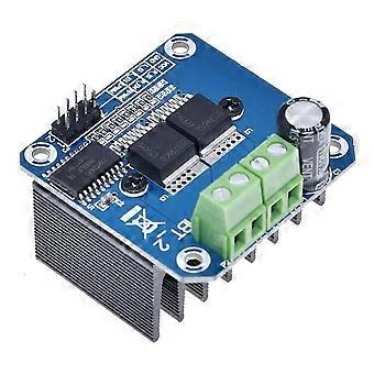
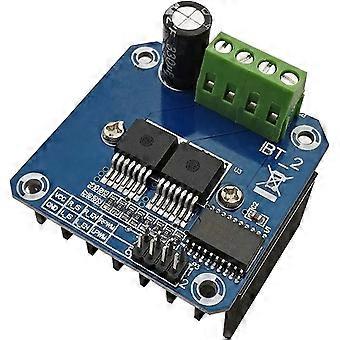
Voltage indication at the motor driver output end helps monitor operating conditions, and the board supports a solderable heat sink for effective thermal management.
Flexible PWMbased control
Forward and reverse control are achievable with two PWM inputs, supporting input frequencies up to 25 kHz for precise speed and direction control.
Onboard power indication
A 5V power indicator on the board provides a quick visual check of supply status.
What it does and how it works
Voltage indication
Displays the motor driver output end voltage, aiding diagnostics and ensuring correct operation before coupling to the motor.
MCU interface
Connect four lines from the MCU: GND, 5V, PWM1, PWM2. This keeps the control interface compact and predictable.
Isolation and protection
An isolation chip provides a 5V isolated power supply, which can share the MCU's 5V supply. This arrangement helps decouple the MCU from motorside noise and faults.
5V isolation with MCU
The 5V isolation helps effectively protect the MCU from voltage or transient events occurring on the motor side.
Power indicator
A dedicated 5V power indicator on the board allows quick verification of the supply status.
Forward/reverse and control signals
To reverse motor direction, use the two PWM inputs. These inputs support PWM frequencies up to 25 kHz, enabling responsive speed and direction control.
Diagnostic output
The design includes an error signal output for fault indication and monitoring.
Interfaces and compatibility
MCU connection
Fourwire interface: GND, 5V, PWM1, PWM2. Compatible with typical 5V microcontroller platforms.
Power and isolation
5V isolated supply that can share the MCU 5V rail, providing flexible deployment in systems where MCU and driver share supply rails.
Performance and physical considerations
PWM capability
Supports input frequencies up to 25 kHz for finegrained motor control.
Isolation and protection
Isolation chip provides a safe barrier between MCU and motor circuitry, reducing risk from noise and faults.
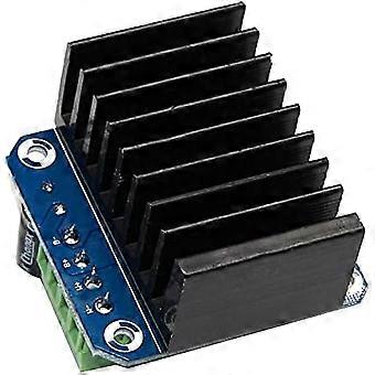
Thermal management
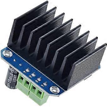
Board design accommodates soldering a heat sink for improved thermal performance when driving larger motors.
Board status indicator
Builtin 5V power indicator for quick system health checks.
Specific use scenarios
Scenario 1: Small robotics project with DC motor
Use the fourline MCU interface (GND, 5V, PWM1, PWM2) and PWM up to 25 kHz to control motor speed and direction, while the isolation protects the MCU from motor noise. The 5V indicator and heat sink compatibility simplify setup and thermal management.
Scenario 2: Industrial conveyor or automated system
Integrate the module to safely drive a motor from a separate control system. The isolated 5V supply and fault signaling help maintain reliability and quick diagnostics in factory environments.
Scenario 3: Hobbyist RC or educational motor experiments
Employ PWM1 and PWM2 for forward/reverse control, benefiting from the simple MCU wiring, builtin indicators, and heat sink mounting options for longer run times and higher current motor tests.
Notes for installation and use
Connect GND, 5V, PWM1, PWM2 from the MCU to the corresponding pins on the driver module.
If needed, attach a heat sink to the motor driver output end to improve heat dissipation during higher current operation.
Ensure the 5V supply feeding the isolation circuit can be shared with the MCU if your system design permits, otherwise provide a separate but compatible 5V supply for isolation.
Observe the 5V power indicator to confirm proper power presence on the board.
Use PWM frequencies up to 25 kHz for driving speed and forward/reverse control, as specified.
This description preserves the original functionality and wiring requirements while presenting clear, benefitfocused information suitable for engineering assessment and practical use.
-
Fruugo ID:
434892538-912417667
-
EAN:
6295761893815
Delivery & Returns
Dispatched within 24 hours
Shipping from China.
We do our best to ensure that the products that you order are delivered to you in full and according to your specifications. However, should you receive an incomplete order, or items different from the ones you ordered, or there is some other reason why you are not satisfied with the order, you may return the order, or any products included in the order, and receive a full refund for the items. View full return policy